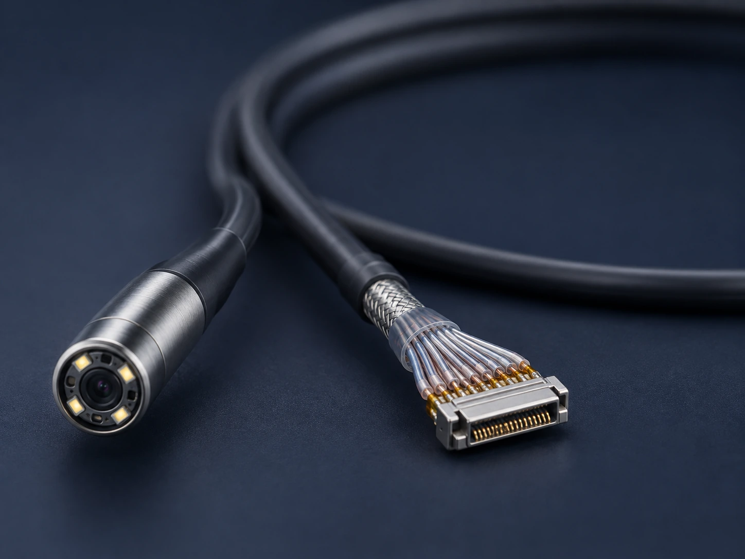
01 Where the difficulty sits
The assembly has to carry power, control and imaging signals through a shaft that also bends. Every conductor added costs diameter and stiffness; every shielding layer added costs the same. The design is a negotiation between image quality and handling.
02 Design considerations
- Conductor count and diameter budget inside the shaft.
- Shielding and crosstalk between imaging and control lines.
- Flex life at the bending section, where failures usually start.
- Termination at the camera head, where space is most constrained.
- Sealing and cleaning requirements at every joint.
We build the cable assembly, not the optical system. Optical performance is specified and verified by the device maker.
03 What to send us
- Shaft cross-section and the space available for conductors.
- Signal list — which lines carry what, and their sensitivity.
- Bending section design and expected cycle count.
- Connector or camera head interface definition.
04 Realistic starting point
Complete endoscope assemblies are usually developed alongside the device, over several iterations. A single sub-assembly — a camera head cable, a control line bundle — is a more practical first project, and a fairer test of whether we fit.